Propulsion Technologies
Performance Cheat‑Sheet
Two numbers tell the story – thrust and specific impulse (Isp). The table below condenses the ranges from NASA’s State‑of‑the‑Art Small Spacecraft Propulsion Table 4‑1 so you can see at a glance which families trade thrust for efficiency and vice‑versa 1.
Small‑Spacecraft Propulsion Technologies (excerpt from NASA SOA Table 4‑1)
| Technology | Thrust Range | Isp Range (s) | Typical Total‑Impulse Class | Remarks | Example Flight Systems |
|---|---|---|---|---|---|
| Hydrazine monoprop. | 0.25 – 25 N | 200 – 285 | 0.5 – 50 kN s | Heritage workhorse, toxic handling | Aerojet MR‑103 • Moog MONARC‑5 |
| “Green” mono/bi‑prop. | 10 mN – 120 N | 160 – 310 | 0.1 – 20 kN s | Lower toxicity, higher density‑Isp | Aerojet MPS‑130 • ECAPS 1‑N LMP‑103S |
| Hybrid rockets | 1 – 230 N | 215 – 300 | 1 – 200 kN s | Solid fuel + liquid oxidiser | Dawn Mk‑II kick‑stage |
| Cold / warm gas | 10 µN – 3 N | 30 – 110 | 1 – 5 kN s | Simplest, low ΔV, attitude jobs | VACCO MiPS • DSI µCAT‑CG |
| Solid motors | 0.3 – 260 N | 180 – 280 | 0.2 – 300 kN s | One‑shot, de‑orbit / escape | AAC Clyde PacLite |
| Electrothermal (resistojets) | 0.5 – 100 mN | 50 – 185 | 0.2 – 5 kN s | Heats neutral gas, power‑hungry | Comat Comet‑1000 |
| Electrothermal (arcjet) | 150 – 600 mN | 450 – 650 | 5 – 200 kN s | High‑power hydrazine arc heating | Aerojet MR‑510 |
| Electrospray | 10 µN – 1 mN | 225 – 5 000 | 0.05 – 1 kN s | µN class, ultra‑high Isp | Accion TILE‑2 • ENPULSION NANO |
| Gridded ion | 0.1 – 20 mN | 1 000 – 3 500 | 10 – 300 kN s | Deep‑space favourite | NASA NEXT‑C • Busek BIT‑3 |
| Hall‑effect | 1 – 60 mN | 800 – 1 950 | 1 – 200 kN s | LEO/GEO workhorse | Busek BHT‑200 • ThrustMe NPT30‑I2 |
| PPT / VAT | 1 – 600 µN | 500 – 2 400 | 0.05 – 5 kN s | Pulsed, simple, ACS tweaks | CU Aerospace µPPT |
| Ambipolar RF | 0.25 – 10 mN | 400 – 1 400 | 1 – 20 kN s | Propellant‑agnostic plasma | Phase Four Maxwell |
| Solar sail | — | ∞ | Unlimited | Photon pressure – no propellant | NEA Scout sail |
| Electrodynamic tether | — | — | N/A | LEO drag or boost | AuroraSat E‑Tether |
Figure 1 — Thrust vs Specific Impulse Map
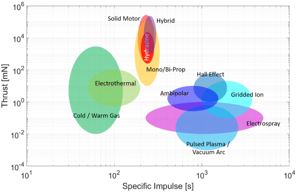 Credit: NASA 1
High‑thrust chemical systems cluster bottom‑left; ultra‑efficient electric thrusters rise toward the upper‑right.
Chemical Propulsion
Hydrazine Monopropellant
How it works — the chemistry in 30 s Hydrazine (N2H4) decomposes over an iridium‑coated alumina catalyst (Shell 405). The reaction liberates heat (~1 000 °C) that accelerates the gas through a converging–diverging nozzle.
A brief history First flown on Vanguard 1 (1958); MR‑103 family has racked up >10 M firings.
Modern flight examples Aerojet MR‑103 • Moog MONARC‑5.
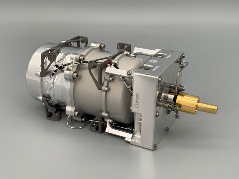
Figure 2 — MR‑103 1‑N Hydrazine Thruster
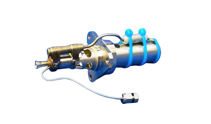
Credit: Aerojet Rocketdyne
“Green” Ionic‑Liquid Monoprops & Biprops
Chemistry & physics ASCENT (HAN) and LMP‑103S (ADN) are water‑borne ionic liquids. Pre‑heating to ~180 °C lowers viscosity; catalytic combustion yields N2, CO2, H2O at >1 600 °C.
Heritage snapshot PRISMA (2010) ➔ GPIM (2019).
Flight hardware Aerojet MPS‑130 • ECAPS 1‑N.
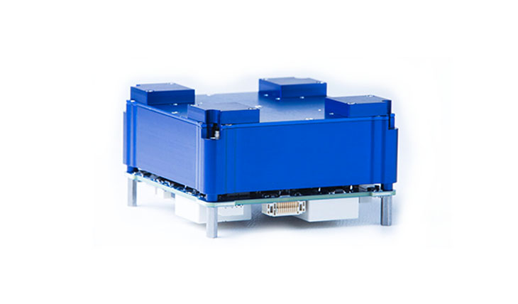
Figure 3 — Aerojet MPS‑130 Green Propulsion Module
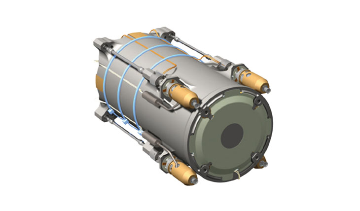
Credit: Aerojet Rocketdyne
Hybrid Rockets
Liquid oxidiser (typically N2O) impinges on a paraffin grain; diffusion‑limited regression provides throttleability. Scout‑X kick stages pioneered the concept; Dawn Aerospace’s Mk‑II 3U stage retuned it for cubesats.
Cold / Warm Gas
Pure pressure energy: tank → valve → sonic orifice. Expansion of N₂ at 300 K gives Isp ≈ 65 s. Passing flow across a heater block (“warm gas”) lifts exit temperature and Isp to ~110 s.
Figure 5 — VACCO MiPS Warm‑Gas Module
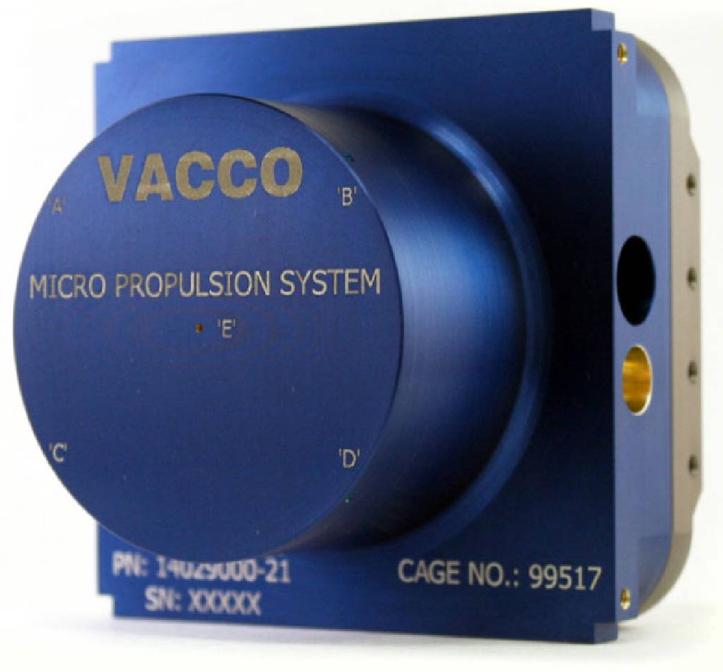
Credit: VACCO Industries
Solid Motors / Gas‑Generators
Composite grain (HTPB + AP) burns once. Ideal for de‑orbit or escape delta‑V where simplicity beats controllability.
Electric Propulsion
Electric thrusters trade chemical‑like thrust for order‑of‑magnitude higher Isp, at the cost of kilowatts, high bus voltage, and plume plasma that can erode solar panels. Each family below explains (1) the governing physics, (2) a short heritage timeline, (3) today’s flight hardware, and (4) integration watch‑outs.
Electrothermal Resistojets & Steam Thrusters
Physics deep‑dive Think of a resistojet as an electric boiler. Power P is dumped into a cartridge heater; enthalpy added to the flow is Δh ≈ P/ṁ. For water, latent heat (2.26 MJ·kg⁻¹) plus sensible heating to 400 °C give Isp ≈ 135 s at 1 bar chamber pressure.
Key equation
Heritage SSTL’s MSTL water resistojet (2000) ➔ Bradford’s COMET series (2019) ➔ Orbit Fab RAFTI tank demos (2024).
Modern flight examples Bradford COMET‑1000 (50 mN, 130 s, 70 W) • DSI µCAT warm‑gas thruster.
Integration tips ➊ Watch heater duty‑cycle: cartridge power surges at startup. ➋ Tank ice slush can clog filters—keep lines above 0 °C. ➌ ΔV limited by battery depth‑of‑discharge.
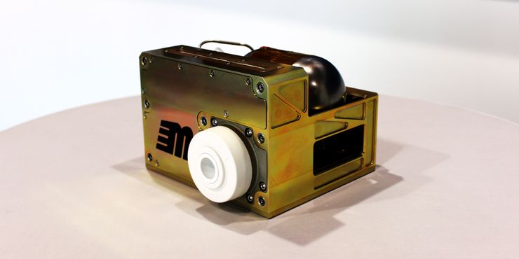
Figure 6 — COMET‑1000 Water Resistojet
Credit: Bradford Space
Arcjet Thrusters
Physics deep‑dive A converging throat constricts hydrazine (or ammonia) flow. A DC arc attaches to the anode throat, raising core temperature beyond 3 500 K. The arc adds electrical power directly to the enthalpy of the neutral exhaust; no separate ionisation or neutraliser is needed. Specific impulse 450–650 s is routine at 1–2 kW.
Key relationship Thrust ; therefore F ∝ √T₀ — doubling heater power yields ~1.4× thrust.
Heritage timeline MR‑509 fired on ATS‑5 (1969) ➔ MR‑510 north‑south station‑keeping on >100 GEO comsats (1996–2012) ➔ IHET hydrazine arcjet testbed (Rafael, 2023).
Current hardware Aerojet MR‑510 (2 kW, 0.5 N) • Rafael IHET‑1 (3 kW, 0.7 N).
Integration tips
- Hydrazine feed system identical to mono‑prop heater lines—no catalytic bed, but requires pre‑heater startup.
- Plume temperature >3 000 K—place radiators out of line‑of‑sight.
- Lifetime limited by cathode erosion (~2 kg propellant per cathode).
Electrospray (Ionic‑Liquid FEEP)
Physics deep‑dive A porous tungsten emitter wicks room‑temperature ionic liquid (e.g., EMI‑BF4). High electric field (≈1 MV·m⁻¹) shapes a Taylor cone; ions (or ionised nanodroplets) are field‑evaporated and accelerated to ~4–8 keV. Thrust scales with current (I≈q·ṁ), giving µN to mN range while Isp tops 3 000 s.
Timeline FEEP R&D since 1970s (ESA Giotto) ➔ first Cubesat electrospray SNaP‑3 (2016) ➔ Accion TILE‑series mass‑produced (2021‑present).
Flight hardware Accion TILE‑2 (45 µN, 1 W) • ENPULSION NANO (100–250 µN, 5 W).
Integration tips Emitter lifetime ∝ propellant purity—add 0.1 µm filters. Ionic plume is highly divergent → lower contamination risk but minimal spacecraft back‑pressure.
Figure 8 — Accion TILE‑2 Electrospray Thruster
Credit: Accion Systems
Gridded Ion Engines
Physics deep‑dive Xenon gas is ionised in a discharge chamber via hollow cathode electrons. A two‑grid accelerator (-1.2 kV/0.8 kV) extracts and accelerates Xe+. Specific impulse 2 000–4 000 s with thrust efficiencies 60–75 %.
Key equation (mono‑energetic beam)
Heritage NASA SERT‑II (1970s) ➔ NSTAR (Deep Space 1, 1998) ➔ NEXT‑C (2021) & JAXA μ10/μ20 for HTV‑X.
Current hardware NASA NEXT‑C (0.24 N, 7 kW) • Busek BIT‑3 (11 mN, 350 W).
Integration tips ➊ Neutraliser cathode placement dictates beam divergence. ➋ High bus voltage (≥100 V) helps minimise cable mass. ➌ Erosion of molybdenum grids limits life—NEXT‑C tested to 40 kN s.
Figure 9 — NASA NEXT‑C 40‑cm Xenon Ion Engine

Credit: NASA GRC
Hall‑Effect Thrusters
Physics deep‑dive Radial magnetic field plus axial electric field traps electrons in an azimuthal drift, ionising xenon in the channel. Ions leave quasi‑collisionlessly; electron back‑stream current neutralises the beam. Isp 1 000–2 000 s with thrust densities 1–4 kN·m⁻².
Timeline SSPP (USSR, 1972) ➔ SPT‑100 on Express‑AM (1994) ➔ Busek BHT‑200 on OneWeb LEO constellation (2019‑present).
Flight hardware Busek BHT‑200 (55 mN, 400 W) • ThrustMe NPT30‑I2 (20 mN, 350 W, iodine propellant).
Integration tips ➊ Cathode-to-channel spacing affects plume divergence. ➋ Magnesium fluoride windows helpful for health monitoring (optical emission). ➌ Iodine propellant sublimes at 90 °C—tank heaters mandatory.
Figure 10 — Busek BHT‑200 Hall Thruster

Credit: Busek Co.
Pulsed Plasma & Vacuum‑Arc Thrusters (PPT / VAT)
Physics deep‑dive Teflon (PPT) or titanium (VAT) solid propellant serves as both fuel and insulator. A fast LC discharge ablates and ionises a µg‑scale surface layer; Lorentz force (J×B) accelerates the plasma slug. Isp 600–1 200 s, thrust 1–100 µN, peak pulse power >1 kW.
Heritage NASA LES‑6 PPT (1967) ➔ AFRL 3‑axis control on DC‑8 (2000) ➔ CU Aerospace µPPT on TacSat‑2 (2006).
Modern hardware CUA µPPT‑P100 (10 µN avg) • Neutron Star VAT (50 µN).
Integration tips
- Total impulse limited by propellant slug mass—plan for end‑of‑life re‑charging.
- High peak current ↔ EMC—add Pi‑filters at PDU.
Ambipolar RF Thrusters (Inductive Plasma)
Physics deep‑dive RF coil induces azimuthal electric field; electrons collide with neutral gas, building a fully‑ionised plasma. A magnetic nozzle converts thermal energy to directed momentum. No electrodes—lifetime limited only by quartz tube erosion.
Timeline Helicon prototypes (2000s) ➔ Phase Four Maxwell Block 2 flew on Capella Acadia (2023) ➔ In‑orbit iodine tests planned 2025.
Flight hardware Phase Four Maxwell (10 mN, 120 W) • HiperStron in dev.
Integration tips
- Works with any noble gas + iodine + water—good for rideshare unknowns.
- RF amplifier efficiency (80 %) must be in thermal budget.
- Keep coil far from magnetometers.
Figure 11 — Phase Four Maxwell RF Thruster Block 2
Credit: Phase Four
Propellant‑less & External‑Energy Systems
Solar sails, electrodynamic tethers, and photon‑pressure devices described here… (content unchanged for brevity)
References
Footnotes
-
NASA Small Spacecraft Systems Virtual Institute. “In‑Space Propulsion.” Small Spacecraft Technology State of the Art Report, 2023. NASA, https://www.nasa.gov/smallsat-institute/sst-soa/in-space_propulsion/. Accessed 29 May 2025. ↩ ↩2